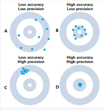
"In machine vision, regardless of the instrument used to measure parameters, there are two key factors: accuracy and repeatability. A basic rule of thumb is that the measuring instrument should be at least ten times better than the process it is measuring. In other words, its repeatability and accuracy should be at least ten times that of the process.
All measuring instruments have a scale composed of many 'ticks' or marks along the scale. In the context of machine vision, the distance between these 'ticks' is the size of a pixel (or sub-pixel). In machine vision, the 'ticks' correspond to resolution but not necessarily to the sensitivity of the machine vision system—the minimum change in measurement value that the system can detect. In machine vision, this corresponds to the increment or resolution of a pixel (or sub-pixel).
When measuring parts using machine vision, there is often a challenge: the edges of the part typically do not fall precisely on one pixel or between two pixels. The influence of the edge typically manifests across several adjacent pixels. Humans cannot distinguish between two edges that fall on the same pixel. Typically, encoded grayscale values represent the average intensity of a pixel.
Edges can be characterized by four attributes:
- Contrast - the cumulative intensity change along the feature representing the edge.
- Width (blurriness) - the size of the interval on the profile where most intensity changes occur.
- Steepness - the slope of the surface within this interval.
- Orientation - the vector angle perpendicular to the edge pixel.
As object edges often span several contiguous pixels with specific grayscale contours (viewing grayscale values as a third-dimensional attribute of spatial data points), any number of mathematical or statistical schemes can be used to infer the edge point's position or establish the edge's position within an increment of valid object distance through the pixels in the object space. For example, viewing grayscale contours as curves, the second derivative of the curve—specific points expected to change—can be calculated and defined as edge pixels.
Different machine vision algorithms utilize various properties of edges to compute the position of the edge within pixels (or sub-pixels). It's worth noting that different algorithms can indeed yield different results in terms of the size of the sub-pixel increment.
Accuracy of the precision
Accuracy is determined by the calibration procedure. In machine vision, like most digital systems, a "calibration" knob changes one "tick" (a pixel or sub-pixel distance) at a time. Each "tick" represents a discrete value change in the system output, which is an increment of the physical size.
For example, a nominal dimension of 0.1 with a tolerance of 0.005. (Total tolerance range of 0.01). Therefore, each "tick" (pixel or sub-pixel distance) of the calibration knob should have a value of 0.01 or 0.001 of 0.1. Hence, half of each step is 0.0005. In other words, the accuracy of the machine vision system should be equal to or better than 0.0005.
As the rule of thumb for repeatability is the same as for accuracy, the system's requirement for repeatability is the same, meaning the repeatability should be equal to the size of a "tick".
While accuracy may not be as critical in a given application since it can be obtained through calibration, repeatability is more crucial as it cannot be corrected through calibration or other means. As observed, the above analysis is considered conservative by many. Therefore, some suggest relaxing repeatability from 10/1 to 5/1.
In some cases, the empirical rule used is that the sum of accuracy and repeatability should be less than one-third of the tolerance band. In practice, regardless of what "rule" is followed, the accuracy or repeatability of the measuring instrument should not equal the tolerance of the measured dimension, in fact, it must be much smaller!
Falenses Optical Perspective
Falenses Optical believes that machine vision with sub-pixel capabilities is often used to meet the practical limits of many metrology applications. In some cases, regardless of the system resolution or theoretical pixel size (field of view divided by the number of pixels in the horizontal/vertical direction), performance approaches the actual limit of machine vision in industrial environments.
In the example application where the part size to be measured is 0.1, given that the full field of view of the camera/machine vision system is applied to that size, the theoretical sub-pixel resolution may be 0.1/1500 (based on a 500 x 500 area camera-based machine vision system and 1/3-pixel resolution sub-pixel capability)."