
Features
·Supports 2K.4K, 8K, 12K.16K and 150 million large target area sensors
·The optical back focus can be moved forward and backward according to customer needs to meet different magnifications
·Large aperture, high contrast, large depth of field, small distortion, and uniform image quality at the edge and center
·The optical structure design is compact and can withstand vibration
Application scope
·Appearance defect detection
·position
·Dimensional measurement
·Character detection
Product naming
Naming rule:LS XXM XXX XXK
Example: LS116M0.5A(D80)
LS 116M 0.5 A (D80)
LS Lens type
116M Focal Length
0.5 Magnification
A Product Serialization
(D80) Supports the largest imaging circle
| 16K Line Scan Lens Specifications | ||||||||||
| Model | Standard Mag | Applicable Mag | Image size (mm) |
Focal Length (mm) |
F.NO | Distortion (TV)(%) |
WD(mm) | Filter screw size | Mount | Camera resolution |
| LS90M02B(D86) | 0.2x | 0.15x-0.3x | 86 | 90 | 5.6 | 0.03 | 516 | 650 | V | 16k,5(3.5)um |
| LS114M10.26A(D66) | 0.26x | 0.23x-0.28x | 66 | 114 | 4.2 | 0.0001 | 498 | 672.2 | V | 16k,3.5um |
| LS116M10.26A(D82) | 0.26x | 0.23x-0.28x | 82 | 116 | 4 | 0.0001 | 663.3 | 874.3 | V | 16k,5um |
| LS116M0.33A(D66) | 0.33x | 0.31x-0.36x | 66 | 116 | 4.2 | 0.001 | 412 | 593 | V | 16k,3.5um |
| LS120M0.33A(D82) | 0.33x | 0.29x-0.38x | 82 | 120 | 4 | 0.005 | 586.4 | 805.5 | V | 16k,5um |
| LS120M0.38A(D82) | 0.38x | 0.32x-0.43x | 82 | 120 | 4 | 0.005 | 482.5 | 712 | V | 16k,5um |
| LS116M0.42A(D66) | 0.42x | 0.38x-0.45x | 66 | 116 | 4.2 | 0.001 | 339.7 | 530.1 | V | 16k,3.5um |
| LS116M0.5A(D66) | 0.5x | 0.46x-0.54x | 66 | 116 | 3.8 | 0.001 | 296.6 | 496 | V | 16k,3.5um |
| LS120M0.5A(D82) | 0.5x | 0.46x-0.54x | 82 | 120 | 4.0 | 0.002 | 390.5 | 637 | V | 16k,5um |
| LS116M0.62A(D82) | 0.62x | 0.59x-0.67x | 82 | 116 | 3.8 | 0.001 | 250 | 459 | V | 16k,5um |
| LS116M0.67A(D66) | 0.67x | 0.65x-0.7x | 66 | 116 | 3.8 | 0.1 | 237.2 | 453.5 | V | 16k,3.5um |
| LS148M0.67A(D82) | 0.67x | 0.6x-0.72x | 82 | 148 | 4.5 | 0.01 | 321.2 | 590 | V | 16k,5um |
| LS116M0.7A(D66) | 0.7x | 0.66x-0.75x | 66 | 116 | 3.8 | 0.008 | 226.7 | 445 | V | 16k,3.5um |
| LS100M0.75A(D66) | 0.75x | 0.7x-0.8x | 66 | 100 | 3.8 | 0.001 | 218.1 | 444.8 | V | 16k,3.5um |
| LS116M0.8A(D82) | 0.8x | 0.75x-0.85x | 82 | 116 | 3.8 | 0.008 | 215 | 440 | V | 16k,3.5um |
| LS116M0.83A(D82) | 0.83x | 0.78x-0.88x | 82 | 116 | 3.8 | 0.001 | 204.1 | 437.1 | V | 16k,3.5um |
| LS116M0.87A(D82) | 0.87x | 0.82x-0.92x | 82 | 116 | 3.8 | 0.005 | 199 | 435 | V | 16k,5um |
| LS116M01.0A(D66) | 1x | 0.93x-1.07x | 66 | 116 | 3.5 | 0.0008 | 183.6 | 439 | V | 16k,3.5um |
| LS116M1.33A(D82) | 1.33x | 1.25x-1.47x | 82 | 116 | 3.8 | 0.001 | 156.36 | 444.5 | V | 16k,5um |
| LS116M1.5A(D82) | 1.5x | 1.3x-1.6x | 84 | 116 | 3.8 | 0.08 | 143.7 | 453.7 | V | 16k,3.5um |
| LS116M1.7A(D82) | 1.7x | 1.65x-1.75x | 84 | 116 | 3.8 | 0.05 | 137.7 | 470 | V | 16k,3.5um |
| LS116M2.0A(D84) | 2x | 1.75x-2.25x | 84 | 116 | 3.8 | 0.001 | 127.1 | 496 | V | 16k,3.5um |
| LS120M3.0A(D82) | 3x | 2.4x-3.8x | 82 | 120 | 4.0 | 0.001 | 143 | 568 | V | 16k,5um |
| LS116M3.0A(D84) | 3x | 2.5x-3.5x | 84 | 116 | 4.2 | 0.001 | 111.3 | 591.4 | V | 16k,5um |
| LS116M4.3B(D88) | 4.37x | 3.8x-4.8x | 88 | 116 | 1.56 | 0.02 | 92 | 699 | V62 | 16k,5um |
| LS116M5.0B(D88) | 5x | 4.5x-5.6x | 88 | 116 | 1.57 | 0.02 | 88.7 | 772.8 | V62 | 16k,5um |
| LS117M6.2B(D88) | 6.2x | 5.6x-6.9x | 88 | 117 | 1.57 | 0.02 | 83.9 | 912.2 | V62 | 16k,5um |
| 12K Line Scan Lens Specifications | ||||||||||
| Model | Standard Mag | Applicable Mag | Image size (mm) |
Focal Length (mm) |
F.NO | Distortion (TV)(%) |
WD(mm) | Filter screw size | Mount | Camera resolution |
| LS100M0.2A(D66) | 0.2x | 0.15x-0.25x | 66 | 100 | 4.5 | 0.005 | 654.8 | 828 | V | 12k,5um |
| LS95M0.05A(D62) | 0.05x | 0.03x-0.08x | 62 | 95 | 4 | 0.005 | 1980 | 2113 | V | 12k,5um |
| LS90M0.1A(D64) | 0.1x | 0.08x-0.14x | 64 | 90 | 4 | 0.01 | 992 | 1123.5 | V | 12k,5um |
| LS116M0.2A(D62 | 0.2x | 0.18x-0.24x | 66 | 116 | 4.5 | 0.01 | 652.4 | 825 | V | 12k,5um |
| LS116M0.3A(D62) | 0.33x | 0.29x-0.4x | 66 | 116 | 4.5 | 0.005 | 415.1 | 599.7 | V | 12k,5um |
| LS116M0.5A(D66) | 0.5x | 0.45 x-0.6x | 66 | 116 | 4.5 | 0.01 | 291.7 | 491.9 | V | 12k,5um |
| LS116M0.7A(D66) | 0.75x | 0.7x-0.85x | 66 | 116 | 4.5 | 0.005 | 209.8 | 429.8 | V | 12k,5um |
| LS116M0.8A(D82) | 0.81x | 0.75x-0.85x | 66 | 116 | 4.5 | 0.005 | 203.8 | 434.7 | V | 12k,5um |
| LS116M1A(D62) | 1x | 0.9x-1.1x | 66 | 116 | 4.5 | 0.005 | 164.2 | 400.6 | V | 12k,5um |
| LS116M1.2A(D62) | 1.24x | 1.19x-1.29x | 66 | 116 | 4.5 | 0.005 | 150 | 434.66 | V | 12k,5um |
| 8K Line Scan Lens Specifications | ||||||||||
| Model | Standard Mag | Applicable Mag | Image size (mm) |
Focal Length (mm) |
F.NO | Distortion (TV)(%) |
WD(mm) | Filter screw size | Mount | Camera resolution |
| LS40M0.05A(D60) | 0.05x | 0.02x-0.16x | 60 | 40 | 4.0 | 0.2 | 819 | M58x0.5 | V | 8k,7u(5u) |
| LS40M017D(D43) | 0.1x | 0.04x-0.33 | 43 | 40 | 3.2 | 0.2 | 421 | V | 8k,5um | |
| LS50M017D(D43 | 0.16x | 0.04-0.33 | 43 | 50 | 2.8 | 0.12 | 335.6 | M43x0.75 | V | 8k,5um |
| LS60M02D(D43) | 0.15x | 0.03x-0.4x | 43 | 60 | 4.0 | 0.5 | 322 | M46x0.75 | V | 8k,5um |
| LS60M02D(D60) | 0.2x | 0.04x-0.33x | 60 | 60 | 4.0 | 0.02 | 404 | M37x0.75 | V | 8k,7um |
| LS80M015D(D62) | 0.15x | 0.13x-0.167x | 62 | 80 | 5.6 | 0.05 | 580 | V | 8k,7um(5um) | |
| LS80M017D(D80) | 0.17x | 0.04x-0.33x | 80 | 80 | 4.0 | 0.08 | 538 | V | 8k,7um | |
| LS80M03B(D64) | 0.3x | 0.2x-0.4x | 64 | 80 | 5.6 | 0.01 | 322 | M37x0.75 | V | 8k,7um |
| LS100M017B(D108) | 0.17x | 0.04x-0.58x | 108 | 100 | 5.6 | 0.05 | 680 | M37x0.75 | V | 8k,7um |
| 4K Line Scan Lens Specifications | ||||||||||
| Model | Standard Mag | Applicable Mag | Image size (mm) |
Focal Length (mm) |
F.NO | Distortion (TV)(%) |
WD(mm) | Filter screw size | Mount | Camera resolution |
| LS20M0.03A(D30) | 0.035x | 0.02x-0.15x | 30 | 20 | 4.5 | 0.5 | 557 | M43x0.75 | V | 4k,7(5)um |
| LS25M01D(30) | 0.1x | 0-0.2x | 30 | 25 | 2.8 | 0.07 | 260 | V | 4k,7(5)um | |
| LS28M0.1A(D30) | 0.1x | 0.05x-0.3x | 30 | 28 | 4.0 | 0.1 | 300 | M35x0.5 | V | 4k,7(5)um |
| LS35MO1D(D28) | 0.1x | 0-0.5x | 30 | 35 | 4.0 | 0.02 | 368 | M27x0.5 | V | 4k,7(5)um |
| LS41M017B(D60) | 0.17x | 0.04x-0.33x | 60 | 40 | 5.6 | 0.55 | 264 | M40.5x0.75 | V | 4k,7(5)um |
| Adapter ring and Focus ring Specifications | |||
| Product | Model | Specifications | |
| Mount | Length | ||
| Focus ring | UNIFOC 55-1 | M54 to M62 | min42.3-max67.3 |
| Focus ring | UNIFOC 55-2 | M54 to M58 | min42.3-max67.3 |
| Focus ring | UNIFOC 23 | UNioc V to V | min17.4-max29.4 |
| Focus ring | UNIFOC 32 | M42 to M58 | min21.4-max42.1 |
| Adapter | ADV495430 | V to M54 | 30 |
| Adapter | AD627219 | M62 to M72 | 19 |
| Adapter | AD727210 | M72 to M72 | 10 |
| Adapter | AD727222 | M72 to M72 | 22 |
| Adapter | AD727250 | M72 to M72 | 50 |
| Adapter | AD527217 | M52 to M72 | 17 |
| Adapter | AD724222 | M72 to M72 | 22 |
| Adapter | AD585810 | M58 to M58 | 10 |
| Adapter | AD585825 | M58 to M58 | 25 |
| Adapter | AD585850 | M58 to M58 | 50 |
| Adapter | AD585800 | M58 to M58 | 100 |
| Adapter | Ad587225 | M58 to M72 | 25 |
| Adapter | Ad587250 | M58 to M72 | 50 |
| Adapter | AD587200 | M58 to M72 | 100 |
| Adapter | AD589525 | M58 to M95 | 25 |
| Adapter | AD589550 | M58 to M95 | 50 |
| Adapter | AD589500 | M58 to M95 | 100 |
| Adapter | ADV38V3806 | V38 to V38 | 6 |
| Adapter | ADV3842065 | V38 to M42 | 6.5 |
| Adapter | ADFM-19 | M58 to F | 19 |
A line scan industrial lens is a specialized type of lens used for line scan cameras or line scan scanners. Line scan cameras and scanners are devices used to capture wide-format images, typically employed in industrial and scientific applications such as inspection, detection, and measurement. Unlike traditional cameras, line scan cameras and scanners capture images by continuously moving in one direction, rather than capturing the entire image at once.
The design of line scan industrial lenses considers the specific requirements of this continuous movement. They typically feature:
-
High resolution: Since line scan cameras and scanners require high-quality image capture, line scan industrial lenses usually have high resolution to ensure clear visibility of image details.
-
Low distortion: To maintain image accuracy, lenses are often designed with minimal distortion.
-
Large aperture: To work in low-light conditions or capture images of fast-moving objects, line scan industrial lenses often feature a large aperture to gather more light.
-
Uniform optical performance: Lenses need to provide consistent image quality across the entire scan line, requiring uniform optical performance.
-
Mechanical stability: Because line scan cameras and scanners often need to run continuously for long periods, line scan industrial lenses require good mechanical stability to maintain image quality and stability over extended periods of use.
These features enable line scan industrial lenses to meet the specific requirements of line scan cameras and scanners, making them essential in industrial and scientific applications.
Concepts of Lens Parameters
|
Resolution (LP/MM) Refers to the number of distinguishable black and white stripes within a 1mm range on the image side. Resolution is expressed in line pairs per millimeter (lp/mm). For example, 100lp/mm means that the distinguishable spacing between black and white stripes is 1/100mm (10um). The width of each black and white stripe is 1/200mm (5um). |
Focal Length f(mm), Back Focal Length/Front Focal Length The focal length refers to the distance between the optical system's center and its focus point. The back focal length is the distance from the vertex of the last lens element to the back focal point, while the front focal length is the distance from the vertex of the first lens element to the front focal point. |
|
Chromatic Aberration: In optical lenses, the magnification of the image can vary based on the wavelength of light, leading to differences in where the image is formed. This variation is called chromatic aberration. Chromatic aberration along the optical axis is referred to as axial chromatic aberration, while chromatic aberration occurring off-axis is called lateral chromatic aberration or magnification chromatic aberration. |
Effective F# This value represents the effective brightness of a lens at a given finite distance, indicating the brightness during actual operation. As the optical magnification (β) increases, the lens becomes darker. The effective F-number (Effective F#) is calculated as V(2×NA) = 1/(2×NA), and Effective F# = (1+β) × Standard F#. |
|
Floating Mechanism: This system is designed to compensate for image aberrations that occur during close-up photography. When a lens is moved (extended) for close-up shots or to adjust object distance, aberrations can vary depending on magnification or shooting distance, sometimes leading to a drop in sharpness. A floating mechanism minimizes the aberrations caused by moving the lens in varying shooting conditions, thereby correcting these aberrations. |
Depth of Focus(DOF) Depth of focus is the distance between the nearest and farthest points where the image remains acceptably sharp as the sensor moves back and forth from the optimal focus point. Unlike depth of field, which is a parameter on the object side, depth of focus is a parameter on the image side of the optical system. |
|
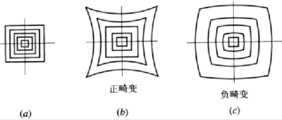
Distortion (%): Distortion is the phenomenon where straight lines appear bent when imaging off-axis points. When straight lines bend inward toward the center, it's known as pincushion distortion. When they bend outward, it's called barrel distortion. |
Telecentric Optical System A telecentric optical system is one where the chief rays are parallel to the optical axis. If the light from the object traveling toward the lens remains parallel to the optical axis, even off-axis, it's called an object-side telecentric system. If the light traveling from the lens toward the image remains parallel to the optical axis, even off-axis, it's known as an image-side telecentric system. |
|
Depth of Field (DoF) Depth of Field is the distance between the nearest and farthest points where the image remains acceptably sharp as the object moves toward or away from the optimal imaging distance. Depth of Field is influenced by factors like the lens's effective F-number, the circle of confusion diameter, and the optical magnification (β). The circle of confusion is the diameter of a blur circle that represents an acceptable level of sharpness. A common standard for an acceptable circle of confusion diameter is 0.04mm. |
Resolution (μm) Resolution is a measurement of the minimum distance between two points before they are no longer distinguishable. For example, a resolution of 1 μm means that two points separated by 1 μm can be resolved. The resolution values in this context refer to the theoretical resolution of a lens. Below is the formula used to calculate the theoretical resolution based on the diffraction limit for an aberration-free lens.
where λ is the design wavelength, typically 550 nm, and NA is the numerical aperture of the lens. |
|
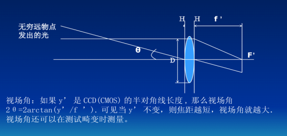
Field of View (mm) Field of view refers to the size of the object that can be captured when the lens is mounted on a camera. The field of view is determined by the sensor size divided by the optical magnification (β). (Example Calculation) If the optical magnification is 0.2x and the camera sensor size is 1/2" (4.8mm length, 6.4mm width): Field of view length = 4.8 / 0.2 = 24 (mm) Field of view width = 6.4 / 0.2 = 32 (mm) |
Working Distance (WD) (mm) Working distance is the distance from the bottom surface of the lens to the object being inspected. |
|
Back Focal Distance (mm) Back focal distance is the distance from the front edge of the lens mount flange to the image plane. |
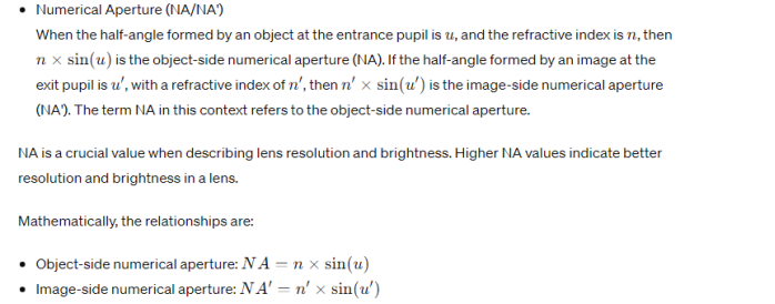
Numerical apertureNA/NA'
|
|
C-Mount Specifications · Name: C-Mount · Standard Outer Diameter: 25.400 mm · Thread Pitch: 32 threads per 25.4 mm · Back Focal Distance: 17.526 mm C-Mount is a standard specification for lens mounts used in cameras and other optical systems. It is characterized by a specific outer diameter, thread pitch, and back focal distance, facilitating compatibility among various lenses and cameras designed with this specification. |
F.NO (F-Number) This parameter represents the light-gathering capability of a lens. It is calculated by dividing the focal length of the lens by the diameter of the entrance pupil D. It can also be derived through the optical magnification from the lens's numerical aperture (NA). A smaller F-number indicates a brighter image. The formula to calculate F-number is: F# = \frac{{f}}{{D}} Where f is the focal length, and D is the diameter of the entrance pupil. |
|
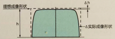
TV Distortion (%) TV distortion refers to the distortion in the vertical direction of a TV screen (chip). A lower value indicates better performance, ideally approaching zero. TV distortion (%) is calculated as: \text{TV distortion (%) = (Distortion Depth/Screen Height) × 100} Where "Distortion Depth" refers to the curvature deviation along the longer edge, and "Screen Height" is the perpendicular measurement of the display.
|
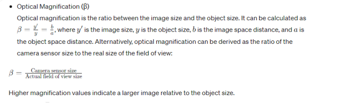
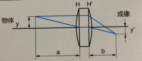
Optical magnification (β)
|